Which set is this?
Building, plant room, asset ID, driver and pump make and model, system served, design documents and applicable requirements.

BCAM FIRE / SYSTEMS EXPLAINED
A visual introduction to the diesel driver, pump and water path—and to the evidence that makes an installed system understandable.
01 / IN THE PLANT ROOM
Installed rooms contain multiple sets, controls, pipework and site constraints. These two photographs show real Australian fire pump installations. The anatomy that follows explains common relationships but does not depict either installation.
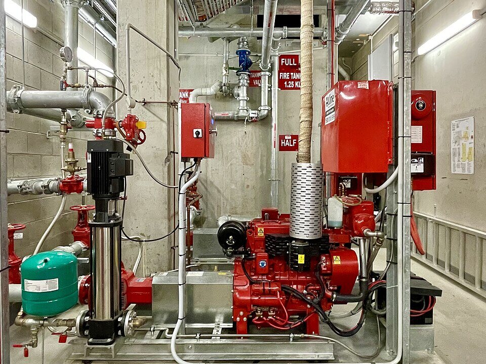
A photographed hydrant pump installation. The equipment identity, duties and arrangement must come from the actual site record.
Photo: Kgbo / Wikimedia Commons · CC BY-SA 4.0. Displayed without alteration.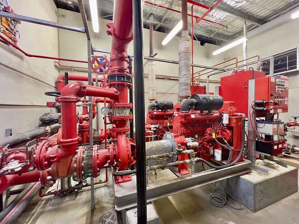
A photographed fire pumps plant room: a fuller context than any isolated product view.
Photo: Kgbo / Wikimedia Commons · CC BY-SA 4.0. Displayed without alteration.01 / OPEN THE ASSEMBLY
Select a part to follow its role. The exploded illustration is a conceptual view of one diesel driven horizontal split case arrangement; it is not a drawing of an installed BCAM asset.
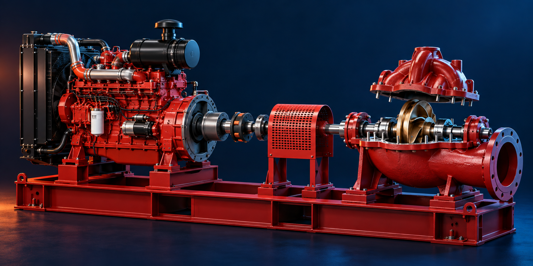 BCAM FIRE / ASSEMBLY CONCEPT
The rotating impeller moves water through the casing. The upper casing is lifted here to reveal the internal relationship. Real pump construction and arrangement vary.
02 / FOLLOW THE WATER
Trace the high level route from source to connected building system. Select a point to see what BCAM would keep identifiable in the record.
The diesel driver turns the impeller when the fire pump is called to operate.
A pressure-maintaining jockey pump may maintain system pressure. A pressure drop can call the main fire pump through its controller; the installed controls and sequence govern what happens.
Conceptual sequence only. The approved hydraulic design, site drawings, equipment documentation and applicable local requirements govern assessment and testing.
02 / GO DEEPER
Move between the driver and pump. The concept illustrations separate many component families; the adjacent parts index explains what to identify on the actual asset.
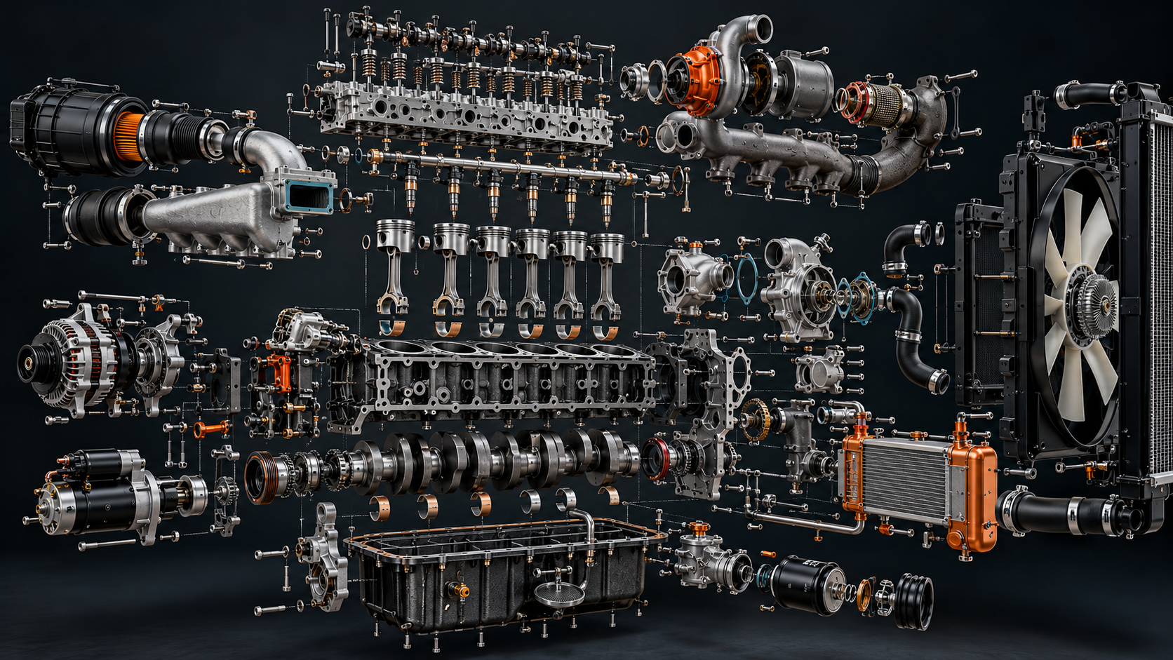
Combustion chambers, coolant passages and the head-to-block joint. Record the exact engine model before using any part diagram.
Connect this to the BCAM asset record →03 / COMPARE COOLING ARRANGEMENTS
A radiator-cooled engine still circulates liquid inside the block; air removes heat at the radiator. A directly air-cooled engine rejects heat at finned metal surfaces. Compare the routes before identifying the installed driver.
A separate raw-water loop from the fire pump passes through the heat exchanger and leaves by the designed outlet. Some drivers add charge-air cooling.
Conceptual pathways only. Inspect the manufacturer’s manual, approved drawings and site conditions before assessing an actual fire pump driver.
05 / THE BCAM RECORD
The illustration helps someone understand the relationship. BCAM connects the installed equipment to a specific place, duty, drawing, observation and accountable outcome.
Building, plant room, asset ID, driver and pump make and model, system served, design documents and applicable requirements.
Dated test and inspection evidence, measured values, faults, access limits and changes to the installation.
Defect, impairment decision, responsible person, repair, retest and closure evidence remain linked to the same asset.
SOURCE NOTES
System relationships are informed by manufacturer guidance from Grundfos on pressure-maintaining pumps and Pentair on diesel-driven split-case fire pumps . Cooling variants follow Clarke’s engine manual ; the direct air-cooled comparison follows Hatz’s air-cooled pump engine range . This is an educational example, not a procedure for operating, testing or certifying any installation.
BCAM FIRE / CONNECTED SYSTEMS